Sand is the only terrain I know that can’t decide what it is. Step on it right and it’s concrete. Step on it wrong and it’s soup. For our EE 579 final project, my team asked: what if a robot could flip that switch on purpose — fluidize the ground for the leg that’s swinging forward, then let it jam solid for the leg that’s pushing off? All inside a single stride.
We built it. We measured it. It didn’t work. This is the honest version, with numbers.
Full test run on the granular testbed — the bounding gait carrying the quadruped across the bead bed.
The bet
Legged locomotion on granular media has a clean piece of physics behind it, from Li, Umbanhowar, Komsuoglu, and Goldman: on dense, packed sand a legged robot does efficient “rotary walking”; on loose, fluid-like sand the same robot degrades into “swimming” — lots of motion, no progress. The substrate’s state is the whole game.
Two more facts from the literature made the bet tempting:
- Vibration fluidizes. Marston et al. showed a vibrating object penetrates sand with dramatically reduced resistance — the grains lose their force chains and flow.
- Vibration compacts — after the fact. Stop shaking a box of grains and they settle denser and stronger than before (Raihane et al. and others). The aftermath of vibration is a firmer packing.
Nobody had combined the two into one gait cycle: shake during swing (low drag for the recovering leg), stop during stance (firm foothold for the pushing leg). Timed, intermittent, synchronized to the stride. Our research question: can a legged robot improve locomotor efficiency by cyclically switching the sand between fluid and solid in sync with its gait?
The machine
Four Dynamixel XL-320 servos, one degree of freedom per leg, on a rigid chassis. The gait is a Buehler clock — the standard trick for legged robots: each stride splits into a slow phase (stance, on the ground) and a fast phase (swing, in the air), set by the slow-phase extent, a phase offset, a duty cycle, and the stride period. Ours ran a bounding gait — front pair and rear pair half a period apart, 4-second period, 0.56 duty cycle.
The vibration system: six 14 mm coin motors — the kind that buzz in a phone — under the chassis, driven by two Adafruit DRV2605L haptic controllers (front pair on hardware I2C, rear pair on bit-banged software I2C, because of course we ran out of hardware buses). An Arduino orchestrated everything: legs in swing → vibrate; touchdown → keep vibrating 500 ms into stance to help the foot settle, then cut it.
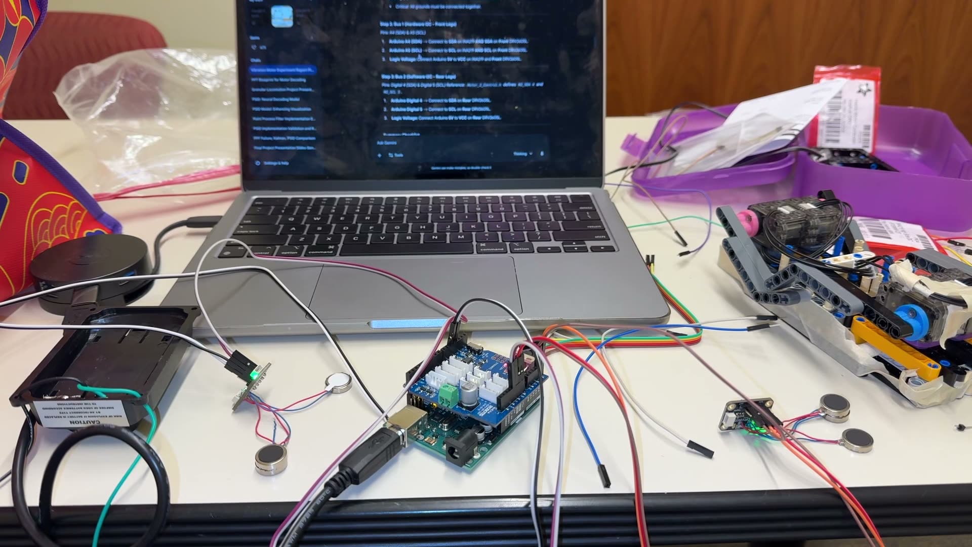 The rig on the workbench: Arduino with the driver shield, coin vibration motors scattered around, and the DRV2605L wiring notes open on the laptop.
The part I’m proudest of isn’t the idea, it’s the instrumentation. The XL-320s report present load, so every 20 ms the firmware logged per-leg torque (load × stall torque) and mechanical power (torque × angular velocity), streaming tab-separated telemetry at 115200 baud. Plus the unglamorous hack the project needed: the XL-320 only positions over 0–300°, so when the Buehler clock commanded an angle inside the dead zone, the firmware flipped that servo to velocity mode, coasted through, and flipped back. Robots are 10% inspiration, 90% dead-zone handling.
The course built toward this honestly. Lab 1 was single-servo trajectories — theta vs. time, theta vs. torque plots. Lab 2 was open playground. Lab 3 was the measurement pipeline: the telemetry discipline, displacement tracking, the “how do you know what you claim” part. The final project was all of it at once, with sand.
The experiment
A wooden box of uniform white beads — macro-scale, spherical, standing in for sand. Zero incline. Cross 2 feet. Control run: bounding gait, no vibration. Experimental run: same gait, timed vibration. Metrics straight from the literature:
- Forward velocity, from video timing.
- Per-leg torque and power, from the servo telemetry.
- Cost of transport:
CoT = P / (W * v)— power over weight times velocity. Dimensionless, the standard efficiency score. Lower is better.
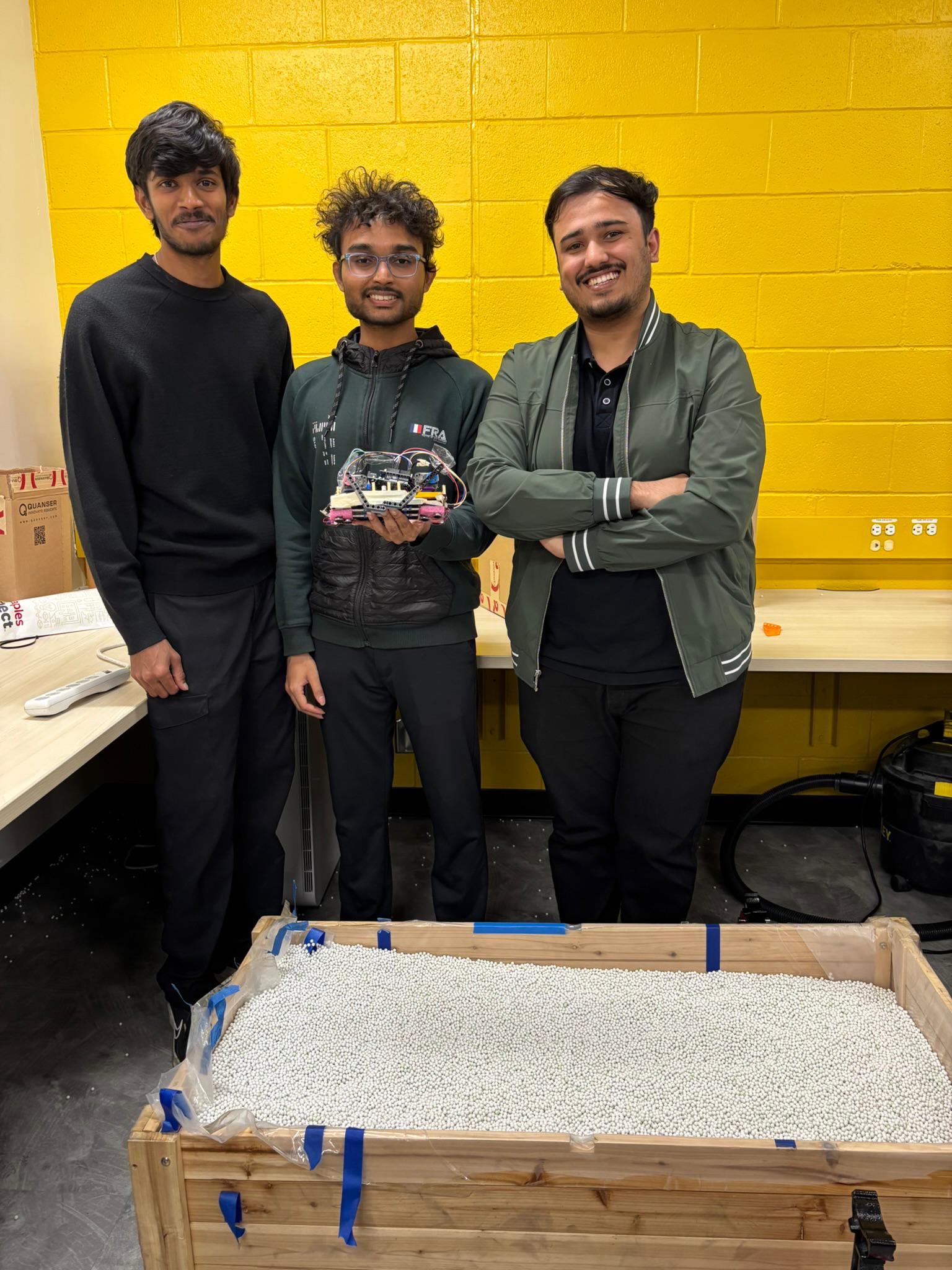 The testbed: a wooden box of beads standing in for loose terrain.
The numbers
| Control (no vibration) | Vibration | |
|---|---|---|
| Robot mass | 0.275 kg | 0.325 kg |
| Time for 2 ft | 35 s | 42 s |
| Leg power | 2.37 W | 2.28 W |
| Vibration motor power | — | 1.3 W (measured, INA219) |
| Yield (peak stance) torque | 0.47–0.49 N·m | 0.47 N·m |
| Swing drag torque | 0.144 N·m | 0.143 N·m |
| Cost of transport | 50 | 49 (legs only) → 77 (honest) |
Read the honest column first. Leg power alone dropped from 2.37 W to 2.28 W — stop there and you’d write “marginal improvement” and move on. That’s the metric lying. The vibration motors drew 1.3 W, measured with an INA219 current sensor — more than half the legs’ power again — and the haptic rig added 50 g to a 275 g robot, an 18% mass penalty before it spent a single joule. Put it all in: CoT 50 → 77. Not a marginal win. A clear loss.
The terrain-interaction numbers back it up: peak stance torque — the ground’s yield force, the foothold quality — didn’t move (0.47–0.49 vs 0.47 N·m). Swing drag didn’t move either (0.144 vs 0.143 N·m). The vibration changed nothing about the sand. It just cost power and weight.
Why it failed
A scaling mismatch, and it’s the most useful thing we learned. Our “sand” was macro-scale beads with real individual inertia. Our vibration source was phone-haptic coin motors. In the literature where vibration fluidizes grains, the vibration is powerful relative to the particle size — ultrasonic shaking on fine powder. We had the ratio inverted: big beads form stable force chains, and a 14 mm coin motor cannot break them. There is a threshold power density for fluidization, and it scales with grain size. We were under it by an order of magnitude, not a rounding error.
What I’d do next
Two paths, both about fixing the ratio: fine silica sand (sub-millimeter grains), where the current motors might actually fluidize; or real actuators — geared eccentric masses, low frequency, high amplitude — that can physically displace the beads we had. The control strategy (timed, gait-synced) is still the right shape. It just needs an actuator that can win the fight it’s picking.
The point
I’m keeping this result because null results with good instrumentation are worth more than positive results with bad instrumentation. We know exactly how much it didn’t work, why, and what would change the answer. That’s not a failed project. That’s a measurement.
Built with Danie Craig Kulandai and Dhyanik Pujara — EE 579, Fall 2025. Firmware and report live in the project repo; the full writeup is on the project page.